

Kit Introduction
This is the Myduino IoT Maker Kit V2, designed specifically for beginners and enthusiasts who want to explore the world of the Internet of Things (IoT). The kit includes a comprehensive selection of NodeMCU ESP32 most popular and versatile electronic components, ideal for building smart projects.
Additionally, we provide detailed tutorials that feature project descriptions, step-by-step instructions, and source code. Working through these projects gives you hands-on experience and a solid foundation in IoT concepts. With this kit, you’ll unlock the ability to interact with and control the physical world through smart devices and sensors.
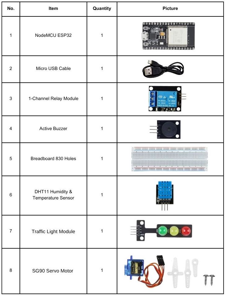
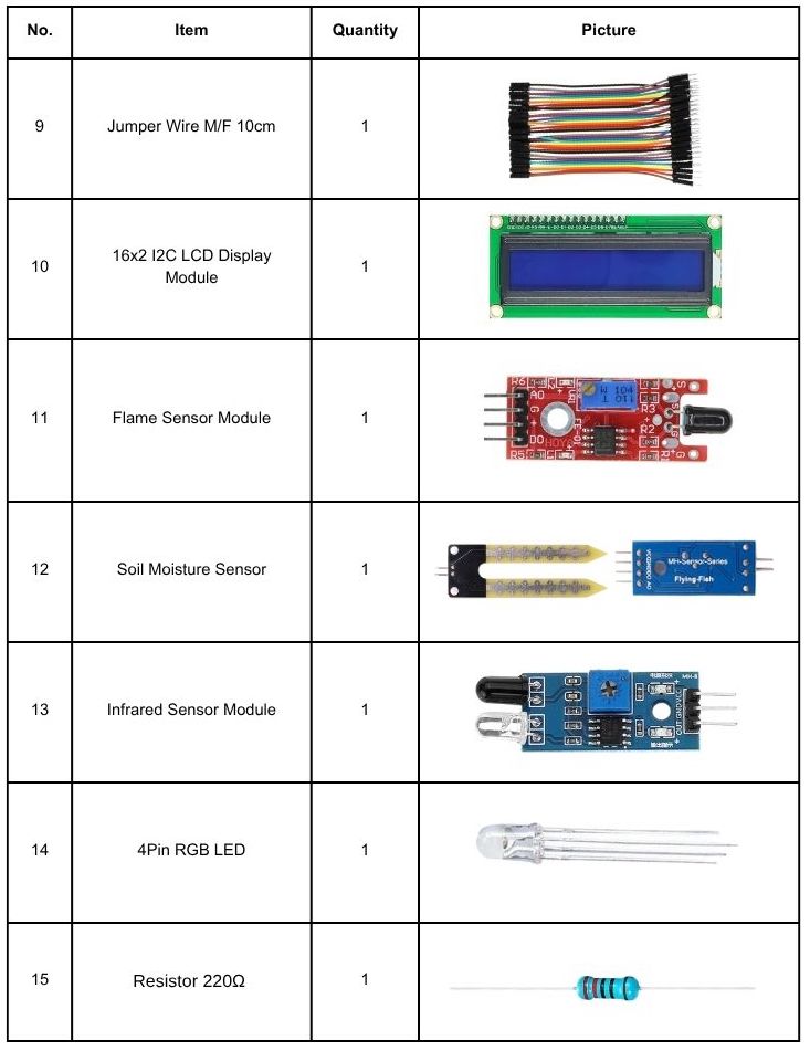
Kit Contents
Introduction to NodeMCU ESP32 Boards
The term ESP32 technically refers to the bare microcontroller chip. However, it’s also commonly used to describe ESP32 development boards. Working with bare ESP32 chips is challenging and impractical, especially for beginners or when testing and prototyping projects. In most cases, it’s much easier and more convenient to use an ESP32 development board.

These development boards include all the essential circuitry needed to power and program the ESP32 chip. They provide a USB connection to your computer, accessible pins for connecting peripherals, built-in LEDs for power and status indicators, a Wi-Fi antenna, and other helpful features. Some boards even come with additional hardware, such as sensors, displays, or a camera, like the ESP32-CAM.
What is the best ESP32 development board for beginners?
For beginners, we recommend using an ESP32 board that has a wide range of available GPIOs and lacks any unnecessary hardware features. It’s also important that it includes a voltage regulator and a USB input for powering the device and uploading code.
In many of our ESP32 projects, we use the ESP32 DEVKIT DOIT board, which we recommend for beginners. There are different versions of this board with various numbers of available pins, including 30, 36, and 38. All versions of the board function similarly.
ESP32 DEVKIT DOIT
We’ll be using the ESP32 DEVKIT DOIT board as a reference. If you have a different board, don’t worry. The information on this page is also compatible with other ESP32 development boards.
The picture below shows the ESP32 DEVKIT DOIT V1 board, version with 30 GPIO pins.

Specifications – ESP32 DEVKIT V1 DOIT
The following table shows a summary of the ESP32 DEVKIT V1 DOIT board features and specifications:
| Number of cores | 2 (dual core) |
| Wi-Fi | 2.4 GHz up to 150 Mbits/s |
| Bluetooth | BLE (Bluetooth Low Energy) and legacy Bluetooth |
| Architecture | 32 bits |
| Clock frequency | Up to 240 MHz |
| RAM | 512 KB |
| Pins | 30, 36, or 38 (depending on the model) |
| Peripherals | Capacitive touch, ADC (analogue to digital converter), DAC (digital to analog converter), I2C (Inter-Integrated Circuit), UART (universal asynchronous receiver/transmitter), CAN 2.0 (Controller Area Network), SPI (Serial Peripheral Interface), I2S (Integrated Inter-IC Sound), RMII (Reduced Media-Independent Interface), PWM (pulse width modulation), and more. |
| Built-in buttons | RESET and BOOT buttons |
| Built-in LEDs | built-in blue LED connected to GPIO2; built-in red LED that shows the board is being powered |
| USB to UART bridge | CP2102 |

This board has a microUSB port that lets you connect it to your computer to upload code or power it up.
It utilises a CP2102 chip (USB-to-UART) to communicate with your computer via a COM port. Some boards use a CH340 chip instead. You’ll need to install the correct driver depending on the chip your board uses so your computer can detect it.
There are also two buttons on the board:
- RESET (EN): Restarts the board.
- BOOT: Puts the board into upload mode (some boards may not have this button).
It also has:
- A blue LED connected to GPIO 2 — useful for testing or debugging.
- A red power LED that turns on when the board is powered.
ESP32 GPIOs Pinout Guide
The ESP32 chip comes with 48 pins with multiple functions. Not all pins are exposed in all ESP32 development boards, and some pins should not be used. The ESP32 DEVKIT V1 DOIT board usually comes with 30 exposed GPIOs that you can use to connect peripherals.
Power Pins
Most boards have these power pins:
- 3V3 – gives 3.3V power
- GND – ground
- VIN – can be used to power the board (if not using USB), or give power to other components (if the board is powered by USB)
GPIO Pins (General Purpose Input/Output)
Each GPIO pin has a number (like GPIO 2, GPIO 4, etc.)—use these numbers in your code. With ESP32, you can choose which pins to use for:
- UART
- I2C
- SPI
This is possible because of a feature called multiplexing, which lets you assign different functions to the same pin through code. Some pins have special functions or limitations, so not all pins are safe to use for every project.

Programming ESP32 with Arduino IDE

To program your boards, you need an IDE to write your code. For beginners, we recommend using Arduino IDE. While it’s not the best IDE, it works well and is simple and intuitive to use for beginners. After getting familiar with Arduino IDE and starting to create more complex projects, you may find it useful to use VS Code with the Platformio extension instead.
If you’re just getting started with the ESP32, start with Arduino IDE.Installing Arduino IDE
To run Arduino IDE, you need to install JAVA on your computer. If you don’t, go to the following website to download and install the latest version: http://java.com/download.
Downloading and Installing Arduino IDE
To download the Arduino IDE, visit the following URL:
Go to the Arduino website and download the version for your operating system.

- Windows: run the file downloaded and follow the instructions in the installation guide.
- Mac OS X: copy the downloaded file into your application folder.
- Linux: extract the downloaded file, and open the arduino-ide file that will launch the IDE.

If you have doubts, you can go to the Arduino Installation Guide.
Installing the ESP32 in Arduino IDE
To install the ESP32 board in your Arduino IDE, follow these instructions:
1. In your Arduino IDE 2, go to File > Preferences.

2. Copy and paste the following line to the Additional Boards Manager URLs field.
https://raw.githubusercontent.com/espressif/arduino-esp32/gh-pages/package_esp32_index.json
Note: if you already have the ESP8266 boards URL, you can separate the URLs with a comma, as follows:
http://arduino.esp8266.com/stable/package_esp8266com_index.json, https://raw.githubusercontent.com/espressif/arduino-esp32/gh-pages/package_esp32_index.json3. Open the Boards Manager. You can go to Tools > Board > Boards Manager… or you can simply click the Boards Manager icon in the left-side corner.

4. Search for ESP32 and press the install button for esp32 by Espressif Systems version 3.X.

That’s it. It should be installed after a few seconds. After this, restart your Arduino IDE.
Then, go to Tools > Board and check that you have ESP32 boards available.

Now, you’re ready to start programming your ESP32 using Arduino IDE.
Testing the Installation and Uploading Code to the ESP32
Now, let’s check if the installation was successful and if we can upload new code to the ESP32 board. We’ll simply upload an
example sketch from the library of available examples.
Connect your ESP32 development board to your computer using a USB cable. If you have an ESP32 DEVKIT DOIT board, the built-in red LED will turn on. This indicates the board is receiving power.

With your Arduino IDE open, follow these steps:
1) Select your Board in Tools > Board menu or on the top drop-down menu, click on “Select other board and port…“

A new window, as shown below, will open. Search for your ESP32 board model.

Select the board model you’re using and the COM port. In our example, we’re using the DOIT ESP32 DEVKIT V1. Click OK when you’re done.

2) Open the following example— it searches for wi-fi networks within the range of your board.
- ESP32: File > Examples > WiFi (ESP32) > WiFiScan
3) A new sketch opens in your Arduino IDE:

4) Press the Upload button in the Arduino IDE. Wait a few seconds while the code compiles and uploads to your board.

Note: if you see a lot of dots on the debugging window, followed by an upload error, that means your board doesn’t go into flashing mode automatically. Click the Upload button again, and when you start seeing the dots on the debugging window, press the onboard BOOT button for a couple of seconds.
5) If everything went as expected, it will upload successfully after a few seconds. You’ll get a similar message:
6) Open the Arduino IDE Serial Monitor at a baud rate of 115200:
7) Press the ESP32 on-board Enable/RESET button and you should see the networks available near your board.

If you’re having issues uploading code to your ESP32 board, we recommend taking a quick look at the following troubleshooting guide: ESP32 Troubleshooting Guide by randomnerdtutorials.com
ESP32 Examples
In your Arduino IDE, you can find multiple examples for the ESP32. First, make sure you have an ESP32 board selected in Tools > Boards. Then, go to File > Examples and check out the examples under the ESP32 section.

Project Details
Project 1: ESP32 DHT11/DHT22 Web Server – Temperature and Humidity using Arduino IDE
Introduction
In this project, you’ll learn how to build an asynchronous ESP32 web server with the DHT11 sensor that displays temperature and humidity using Arduino IDE.

The web server we’ll build updates the readings automatically without the need to refresh the web page.
With this project you’ll learn:
- How to read temperature and humidity from DHT sensors;
- Build an asynchronous web server using the ESPAsyncWebServer library;
- Update the sensor readings automatically without the need to refresh the web page.
Parts Required
Resources
- ESP32 DHT11/DHT22 Web Server – Temperature and Humidity using Arduino IDE, by Random Nerd Tutorials
Project 2: ESP32 Relay Module – Control AC Appliances (Web Server)
Introduction
Using a relay with the ESP32 is a great way to control AC household appliances remotely. This tutorial explains how to control a relay module
with the ESP32. We’ll take a look at how a relay module works, how to connect the relay to the ESP32 and build a web server to control a relay remotely (or as many relays as you want).

Parts Required
Resources
- ESP32 Relay Module – Control AC Appliances (Web Server), by Random Nerd Tutorials
Project 3: How to make a plant watering system with ESP32 board and Blynk app
Introduction
Gardening is a very gratifying hobby. However, because of our busy lifestyles, plants in our gardens might not always get the attention they deserve. What if we could remotely monitor their conditions and give them the care they need? There is a way! In this tutorial, we are going to create an IoT-based smart gardening system using the Blynk App.
This smart garden project is a plant environment monitoring system that monitors soil moisture level, air temperature, humidity, and water level. Then, depending on the conditions, the system allows users to deliver what is needed remotely through a mobile app. Moreover, this system can be scaled and expanded to automate the entire gardening process!

Parts Required
- NodeMCU ESP32 CP2102 board
- 1 Channel Low-Level Trigger Relay Module 5V
- Jumper wires
- DHT11 Temperature and Humidity Sensor
- Water Level Sensor
- Soil Moisture Sensor
- Breadboard 830 Holes
Resources
- How to Create an IoT Smart Garden Using ESP32 and Blynk, by Maker.pro
Project 4: IoT-Based Temperature Monitoring System Using ESP32 With Blynk App
Introduction
The Internet of Things (IoT) allows us to build smart systems that can connect and share data. In this project, we create an IoT-based temperature monitoring system using an ESP32 microcontroller and the Blynk app. The system uses DHT11 and DS18B20 sensors to measure temperature, and a 16×2 LCD to show the readings. Through the Blynk app, you can monitor the temperature remotely in real time. This project shows how hardware, software, and cloud technology work together to build an efficient temperature monitoring system.

Parts Required
- NodeMCU ESP32 CP2102 board
- Jumper wires
- DHT11 Sensor
- I2C 16×2 LCD Blue/Green Backlight
- DS18B20 Waterproof Temperature Sensor
- Breadboard 830 Holes
- Resistor 4.7k Ohm
Resources
- IoT-Based Temperature Monitoring System Using ESP32 With Blynk App, by justdoelectronics.com
Project 5: LED Blink With ESP32 and Blynk
Introduction
In this Project, We Will Build A Small Home Automation System using ESP32 and the Blynk App. We will use the Arduino IDE Software for programming. We control the home applications wirelessly. Also, we show how to control the LED over the internet using the Blynk application. So we make this tutorial the basis for the projects. I will create more projects in future.

Parts Required
Resources
- LED Blink With ESP32 and Blynkr, by justdoelectronics.com
Project 6: ESP32 Servo Motor Web Server with Arduino IDE
Introduction
In this tutorial, you’ll learn how to create a web server using the ESP32 to control a servo motor’s position with a slider. We’ll start by exploring how to control a servo using the ESP32, and then proceed to building the web server interface.

Parts Required
Resources
- ESP32 Servo Motor Web Server with Arduino IDE, by randomnerdtutorials.com
Project 7: Intelligent flame detection system with ESP32
Introduction
An intelligent flame detection system uses smart sensors and advanced software to detect and analyze flames. It combines infrared and ultraviolet sensors to identify fire and uses image processing to study the flame’s shape, size, and color — helping to tell real fires apart from false alarms. This system is more accurate and reliable than traditional flame detectors and can work together with fire alarms or sprinkler systems for complete fire protection.

Parts Required
- NodeMCU ESP32 CP2102 board
- Jumper wires
- Flame Infrared Sensor
- Traffic Light Module
- Active Buzzer
- Breadboard 830 Holes
Resources
- Intelligent flame detection system with ESP32, by robotique.tech
Project 8: Interface ESP32 with Infrared(IR) Sensor Module
Introduction
Let us go into the exciting part about how we could control our Infrared (IR) Sensor with our ESP32 microcontroller using the Arduino framework. We are going to create two simple projects that will display how useful this electronic component is. Let us go into the exciting part about how we could control our Infrared (IR) Sensor with our ESP32 microcontroller using the Arduino framework. We are going to create two simple projects that will display how useful this electronic component is.

Parts Required
- NodeMCU ESP32 CP2102 board
- Jumper wires
- Traffic Light Module
- Breadboard 830 Holes
- I2C 16×2 LCD Blue/Green Backlight
- (IR) Infrared Obstacle Avoidance Sensor
Resources
- Interface ESP32 with Infrared(IR) Sensor Module, by donskytech.com
Buy from
- Myduino IoT Maker Kit V2 NodeMCU ESP32 from Myduino.com


