

Kit Introduction
This is the Myduino IoT Maker Kit, designed specifically for beginners and enthusiasts who want to explore the Internet of Things (IoT). The kit includes a comprehensive selection of Arduino’s most popular and versatile electronic components, ideal for building smart projects.
Additionally, we provide detailed tutorials that feature project descriptions, step-by-step instructions, and source codes. Working through these projects gives you hands-on experience and a solid foundation in IoT concepts. With this kit, you’ll unlock the ability to interact with and control the physical world through smart devices and sensors.
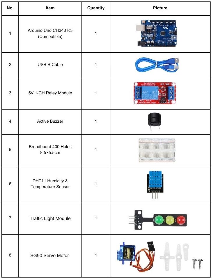
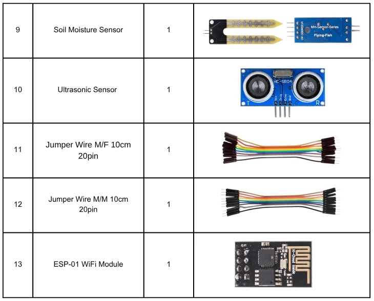
Kit Contents
Introduction to Arduino Uno R3 CH340 (Compatible)
This is a low-cost version of Arduino UNO compatible, using CH340 as a USB to UART chip, so you have more reasons to kick start the digital making. This UNO-compatible board is fully compatible with Arduino UNO R3, which is, yes, R3. Basically, the changes that you might notice are the CH340 driver, which you can download and install from here: Windows, Mac OS, Linux (pre-installed). Other than that, everything is compatible, the shields and the sketches.
Arduino is an open-source physical computing platform based on a simple i/o board and a development environment that implements the Processing/Wiring language. Arduino can be used to develop stand-alone interactive objects or can be connected to software on your computer (e.g. Flash, Processing, MaxMSP). The open-source IDE can be downloaded for free (currently supports Mac OS X, Windows, and Linux).

Specification/Feature
- Microcontroller: ATmega328P
- Operating Voltage: 5VDC
- Input Voltage (recommended): 7-12V through DC jack
- Input Voltage (limits): 6-20V through DC jack
- Digital I/O Pins: 14 (of which 6 provide PWM output)
- Analog Input Pins: 6
- DC Current per I/O Pin: 40 mA
- DC Current for 3.3V Pin: 50 mA
- Flash Memory: 32 KB of which 1 KB used by the bootloader
- SRAM: 2 KB
- EEPROM: 1 KB
- Clock Speed: 16 MHz
- CH340 as USB to UART IC
- USB B type socket for USB power and interface
Arduino Uno R3 (Compatible) Pinout

Getting Started with Arduino
Installing Arduino Software
When you get the REV3 development board, first you should install the Arduino software and driver.
We usually use the Windows software Arduino 1.5.6 version. You can download it from the link below:
https://www.arduino.cc/en/Main/OldSoftwareReleases#1.5.x
Or you can browse the ARDUINO website to download the latest version from this link, https://www.arduino.cc, pop up the following interface.

Then click the SOFTWARE on the browse bar, you will have two options ONLINE TOOLS and DOWNLOADS.

Click DOWNLOADS, it will appear the latest software version of ARDUINO 1.8.5 shown as below.

On this software page, on the right side you can see the version of development software for different operating systems. ARDUINO has a powerful compatibility. You should download the software that is compatible with the operating system of your computer.
We will take WINDOWS system as an example here. There are also two options under Windows system, one is installed version, the other is non-installed version. For the simple installed version, first click Windows Installer, you will get the following page.


This way you just need to click JUST DOWNLOAD, then click the downloaded file to install it.
For the non-installed version, first, click the Windows ZIP file, you will also get the pop-up interface as the above figure.
Click JUST DOWNLOAD, and when the ZIP file is downloaded well to your computer, you can directly unzip the file and click the icon of ARDUINO software to start it.
Installing Arduino (Windows)
Install Arduino with the exe. Installation package. Here we provide you with Arduino-1.5.6-r2-windows package, you can directly click the icon to install it.

Click“I Agree”to see the following interface.

Click “Next”. Pop up the interface below.

You can press Browse… to choose an installation path or directly type in the directory you want.
Then click “Install” to initiate installation.

Wait for the installing process, if appear the interface of Window Security, just continue to click Install to finish the installation.

All right, up to now, you have completed the Arduino setup! The following icon will appear on your PC desktop.

Double-click the icon of Arduino to enter the desired development environment shown as below.

The functions of each button on the Toolbar are listed below:

Installing Driver
Next, we will introduce the driver installation for the development board. The driver installation may have slight differences in different computer systems. So in the following let’s move on to the driver installation in the WIN 7 system.
The Arduino folder contains both the Arduino program itself and the drivers that allow the Arduino to be connected to your computer by a USB cable. Before we launch the Arduino software, you are going to install the USB drivers.
Plug one end of your USB cable into the Arduino and the other into a USB socket on your computer.
When you connect the REV3 board to your computer for the first time, right-click the icon of your “Computer” —>for “Properties”—> click “Device manager”, under “Other Devices”, you should see an icon for “Unknown device” with a little yellow warning triangle next to it. This is your Arduino.

Then right-click on the device and select the top menu option (Update Driver Software…) shown as the figure below..

It will then be prompted to either “Search Automatically for updated driversoftware” or “Browse my computer for driver software”. Shown as below.
In this page, select “Browse my computer for driver software”.

After that, select the option to browseand navigate to the “drivers” folder of Arduino installation.

Click “Next” and you may get a security warning, if so, allow the software to be installed. Shown as below.

Once the software has been installed, you will get a confirmation message. Installation completed, click “Close”.

Up to now, the driver is installed well. Then you can right click “Computer” —>“Properties”—>“Device manager”, you should see the device as the figure shown below.

How to install CH340 driver on Windows
CH340 is a USB to TTL serial converter chip that is included in several development boards, such as Arduino NANO, Arduino MEGA, ESP8266 NodeMCU V3, and CH340 adapter modules. With this chip, these boards don’t need a programmer. The chip comes in several variants, including Ch340C, Ch340G, Ch340B, Ch340T, and others.

Checking whether the CH340 driver is installed
The easiest way to know if the CH340 driver is installed or not when using Arduino boards is to plug the given board into your computer USB port and open the Arduino IDE. Then check for COM Port under Tools as shown below.

If the CH340 driver is not installed then you will not be able to select COM Ports in the Arduino IDE.
Alternatively, for USB to TTL adapter modules, you can check the Windows Device Manager after plugging the device into your PC.

The USB serial device will appear with a danger symbol meaning that it is not being recognized by the computer therefore you need to either install or update the CH340 driver.
How to install CH340 driver
- First, you need to download the CH340 driver for Windows which can be obtained from various sources even from the manufacturers site.
- Unzip the downloaded file and run the installer by double-clicking on the unzipped file. A new window opens where the necessary files are extracted and when done, the driver installer window opens where you click install to begin installing the CH340 driver.

After installing the driver, a “Driver install success!” message pops up. Click OK and close all the windows.

Now you can restart the Arduino IDE and you should now be able to see the COM port where the CH340 device is plugged into the PC.

Also, if the CH340 driver has been installed correctly, when you check the Device Manager after connecting your board to a computer, you can see the USB-serial CH340 COM port listed with the corresponding port number.

Updating CH340 driver in Windows Device Manager
Sometimes the CH340 driver may be installed but corrupted and therefore will cause the plugged device not to work properly. In such a situation you need to update the driver.
- First download the CH340 driver
- Go to the Windows Device Manager.
- Under Other devices right click on the USB serial device with issues.
- Click on Update driver.
A new pane opens where you select how you want to search for the driver. Select Browse my computer for drivers.

Browse to the directory where you stored the downloaded and extracted zip file for CH340 driver.

Click Next and the driver will be updated and after the update, a message will show that the CH340 driver has been updated successfully.

REV3 Platform
Overview
It is very simple. You can use only a main board and a USB cable to display the “Hello World!”. It is a communication experiment between the control board and PC. This is an entry experiment for you to enter the Arduino programming world.
Note that need to use a serial communication software, Arduino IDE.
In the above part, you can check the detailed use of Arduino IDE.
Component Required
- Arduino Uno CH340 R3 (Compatible) x 1
- USB cable x 1
Component Introduction
The Arduino Uno CH340 R3 (Compatible) is a microcontroller board designed for ease of use and compatibility with the Arduino Uno R3 platform. It features the CH340 USB-to-serial chip, which requires a specific driver for USB communication.
It includes 14 digital input/output pins (6 of which support PWM output), 6 analog inputs, a 16 MHz quartz crystal, a USB Type-B connection, a power jack, 2 ICSP headers, and a reset button.
This board provides all the necessary components to support the microcontroller. Simply connect it to a computer via USB (CH340 driver required) or power it using an AC-to-DC adapter or battery to start your projects.
Connect It Up
Connect the REV3 board to your computer using the USB cable. The green power LED should go on.

Upload the Code
Below is an example code for displaying the Hello World!

Select the Arduino Board
Open the Arduino IDE, you’ll need to click the “Tools”, then select the Board that corresponds to your Arduino.

Select your serial port
Select the serial device of the Arduino board from the Tools | Serial Port menu.
Note: to avoid errors, the COM Port should keep the same as the Ports shown on Device Manager.


Then click verify button to check the errors. If compiling successfully, the message “Done compiling.” will appear in the status bar.

After that, click the “Upload” button to upload the code. Wait a few seconds – you should see the RX and TX leds on the board flashing. If the upload is successful, the message “Done uploading.” will appear in the status bar.
(Note: If you have an Arduino Mini, NG, or other board, you’ll need to physically present the reset button on the board immediately before pressing the upload button.)

Open the Serial Monitor
After that, click the serial monitor button to open the serial monitor.

Then set the baud rate as 9600, enter an “R” and click Send, you should see the RX led on the board blink once, and then D13 led blink once, finally “Hello World!” is showed on the monitor, and TX led blink once.
Congrats! Your first simple program is complete.

Project Details
Project 1: Monitoring Temperature Remotely with Blynk for Dummies
Introduction
The project Monitoring Temperature Remotely with Blynk for Dummies serves as an easy-to-follow guide for beginners interested in building an IoT-based temperature monitoring system. It utilizes a DHT-11 sensor to measure temperature and humidity, along with an ESP8266 WiFi module for seamless connectivity. The Blynk platform is used to display real-time data on a smartphone.
This comprehensive tutorial provides step-by-step instructions for assembling the hardware, configuring the software, and designing an intuitive user interface within the Blynk app. Tailored for individuals with a background in mechanics and hydraulics, this project offers a practical introduction to IoT and home automation, enabling users to effortlessly monitor the temperature in their living room from anywhere.

Parts Required
- Arduino Uno R3 CH340 (Compatible Board)
- Jumper wires
- DHT11 Temperature and Humidity Sensor
- Breadboard 400 Holes
- ESP8266 ESP-01S Wireless Module Serial Transceiver
Resources
- Monitoring Temperature Remotely with Blynk for Dummies, by Hackster.io
Project 2: Blynk Home Automation using ESP8266-01 and Arduino UNO
Introduction
The project Blynk Home Automation using ESP8266-01 and Arduino UNO offers a comprehensive guide to building a home automation system that allows users to control household appliances via the internet using the Blynk mobile application. This project integrates manual control through physical switches and remote operation through the Blynk app, providing versatile management of devices such as lights and fans.
The tutorial covers essential components, including the Arduino UNO, ESP8266-01 WiFi module, and a 4-channel relay driver, and provides detailed instructions on hardware assembly, circuit connections, and software configuration. By following this guide, users can create a functional home automation system that enhances convenience and exemplifies the practical application of IoT technologies in everyday life.

Parts Required
- Arduino Uno R3 CH340 (Compatible Board)
- ESP8266 ESP-01S Wireless Module Serial Transceiver
- Breadboard 400 Holes
- Jumper wires
- 1 Channel Low-Level Trigger Relay Module 5V
- SPST Rocker Switch
- Resistor 10k
- AC bulb holder
- AC bulb
Resources
- Blynk Home Automation using ESP8266-01 and Arduino UNO, by MyEngineeringStuffs
Project 3: Remote Relay Controller with Blynk
Introduction
The Remote Relay Controller with Blynk project is designed to help users create a system that remotely controls a relay module via the Blynk application. This project integrates an Arduino UNO Board an ESP8266 WiFi module, and a 5V relay module to enable wireless control of devices. Users will learn to configure the Blynk app, establish communication between hardware components, and develop a functional remote relay controller. This project serves as a practical introduction to IoT applications, demonstrating how to manage devices remotely using a smartphone.

Parts Required
- Arduino Uno R3 CH340 (Compatible Board)
- ESP8266 ESP-01S Wireless Module Serial Transceiver
- Breadboard 400 Holes
- Jumper wires
- 5V LED Traffic Light Module
- 1 Channel Low-Level Trigger Relay Module 5V
Resources
- Remote Relay Controller with Blynk, by Sunfounder
Project 4: Plant Monitor with Blynk
Introduction
The Plant Monitor with Blynk project is designed to help users create a system that monitors environmental conditions for plants. This project utilizes an Arduino UNO board, an ESP8266 WiFi module, a DHT11 temperature and humidity sensor, and a capacitive soil moisture sensor to collect data on temperature, humidity, light intensity, and soil moisture levels.
The collected data is then transmitted to the Blynk application, where users can remotely monitor their plants’ conditions in real time. The Blynk app provides a user-friendly interface, displaying the data and offering suggestions based on soil moisture levels to help maintain optimal plant health. This project serves as a practical introduction to IoT applications, demonstrating how to integrate hardware and software to remotely monitor and manage environmental conditions for plants.

Parts Required
- Arduino Uno R3 CH340 (Compatible Board)
- ESP8266 ESP-01S Wireless Module Serial Transceiver
- Breadboard 400 Holes
- Jumper wires
- DHT11 Temperature and Humidity Sensor
- Soil Moisture Resistive Sensor
Resources
- Plant Monitor with Blynk, by Sunfounder
Project 5: Flame Alert System with Blynk
Introduction
The Flame Alert System with Blynk project is designed to help users create a home fire alarm system that can be monitored remotely via the Blynk application. This project utilizes an Arduino UNO board, an ESP8266 WiFi module, and a flame sensor module to detect potential fires. Upon detecting a flame, the system sends real-time alerts to the user’s smartphone through the Blynk app, enabling immediate awareness and response. The tutorial provides detailed instructions on building the circuit, configuring the Blynk app—including setting up templates, data streams, and events—and running the necessary code. This project serves as a practical introduction to IoT applications, demonstrating how to integrate hardware and software to enhance home safety through remote monitoring and alert systems.

Parts Required
- Arduino Uno R3 CH340 (Compatible Board)
- ESP8266 ESP-01S Wireless Module Serial Transceiver
- Breadboard 400 Holes
- Jumper wires
- Flame Infrared Sensor
Resources
- Flame Alert System with Blynk, by Sunfounder
Project 6: ESP8266 Based Webserver to Control Servo Motor from Webpage
Introduction
The ESP8266 Based Webserver to Control Servo Motor from Webpage project demonstrates how to remotely control a servo motor using an ESP8266 Wi-Fi module and an Arduino Uno. By setting up a web server on the ESP8266, users can manipulate the servo motor’s position through a simple web interface accessible from any device with internet connectivity. This project provides a practical introduction to IoT applications, showcasing how to integrate hardware and software for remote device management.

Parts Required
- Arduino Uno R3 CH340 (Compatible Board)
- Breadboard 400 Holes
- ESP8266 ESP-01S Wireless Module Serial Transceiver
- Jumper wires
- SG90 Micro Servo Motor
Resources
- ESP8266 Based Webserver to Control Servo Motor from Webpage, by IoIdesign pro
Buy From
- Myduino IoT Maker Kit NodeMCU Uno R3 (Compatible) from Myduino.com


